
Tel: 86-574-63620701
Fax: 86-574-63621610
Email: support@yutai-elec.com
website: en.yutai-elec.com
Address: No.46, Dongshan Middle Road, Guanhaiwei town, Cixi City, Zhejiang Province

1. Overview
As early as 1999, Ethernet power supply is no longer a new concept. In fact, at that time, there were many companies that provided dedicated solutions, including 3Com, powerdsine and Cisco. However, a relatively new idea is to develop an industrial standard to ensure full interoperability between various devices.
IEEE began to develop this standard in 1999, and the earliest participating manufacturers are 3Com, Intel, powerdsine, Nortel, mitel and national semiconductor. However, the shortcomings of the standard have been restricting the expansion of the market. Until June 2003, IEEE approved the 802.3af standard, which clearly defined the power detection and control matters in the remote system, and the way that routers, switches and hubs supply power to IP phones, security systems, wireless LAN access points and other devices through Ethernet cables.
2. Key technologies of Poe
1) System composition and power supply characteristic parameters of Poe
A complete Poe system includes two parts: PSE (power sourcing equipment) and Pd (power device).
PSE equipment is the power supply equipment for Ethernet client equipment, and also the manager of the whole Poe Ethernet power supply process. PD equipment is the PSE load that receives power supply, that is, the client equipment of Poe system, such as IP phone, network security camera, AP, PDA or mobile phone charger and many other Ethernet equipment (in fact, any equipment with power no more than 13W can obtain corresponding power from RJ45 socket).
Based on IEEE 802.3af standard, the two sides establish information connection about PD connection, type of RJ45 transformer equipment, power consumption level, etc., and supply power to PD through Ethernet according to PSE.
The main power supply characteristic parameters of Poe standard power supply system are:
a. The voltage is between 44-57v, and the typical value is 48V.
b. The maximum allowable current is 550mA and the maximum starting current is 500mA.
c. The typical working current is 10-350ma, and the overload detection current is 350-500ma.
d. Under no-load condition, the maximum required current is 5mA.
e. Provide PD equipment with five levels of electric power requests of 3.84-12.95w, with the maximum not exceeding 13W.
A detailed description of the five levels of power:
The IEEE 802.3af Poe standard allows designers to provide up to 12.95w of power to consumers (PDS) over Ethernet cables, while meeting the requirements of safety extra low voltage (SELV).
According to IEEE 802.3af standard, PD can be divided into four different levels according to the required power (the fifth level class 4 is reserved for the new standard of higher power).
The maximum working power required for Class 0 equipment is 0 ~ 12.95w
The working power required by class 1 equipment is 0 ~ 3.84w;
Class 2 equipment requires working power between 3.85w and 6.49w;
The power range of class 3 equipment is between 6.5 and 12.95w.
Designers can assign their equipment to a specific level based on power requirements. The low-cost solution can use the general default level specification (Class 0), which means that the PD needs up to 12.95w of working power.
2) Working process of Poe power supply
In the grading stage, PSE will apply 15-20v voltage to PD, and determine the specific grade of PD by measuring the current. In this stage, the power supply part of PD will be kept in a passive state by the undervoltage locking (UVLO) circuit, so as to isolate the switch stage until the feature and classification stage are completed. Once the classification is completed, PSE will provide full working voltage to PD.
When PSE power supply terminal equipment is arranged in a network, Poe Ethernet power supply process is as follows:
Detection: first, PSE will send a test voltage to the equipment in the network to detect a 24.9k Ω common mode resistance in the electrified equipment. The test signal starts at 2.5V and then rises to 10V, which will help compensate for the loss of the Cat-5 cable's own impedance. Because this cable can be up to 100m long. If the PSE detects an appropriate impedance characteristic (24.9k Ω) from the PD, it will continue to raise the voltage. If the characteristic impedance is not detected, the PSE will not power up the cable.
The zener diode in the circuit of the receiving equipment will ensure that the rest of the system will not be interfered by the test signal.
PD terminal equipment classification: when PD is detected, PSE will apply 15-20v voltage to PD, and determine the specific level of PD by measuring the current. The price of RJ45 transformer is defined as zero level if no other grading circuit is found except for the first level resistance. In this stage, the power supply part of PD will be kept in a passive state by the undervoltage locking (UVLO) circuit, so as to isolate the switch stage until the feature and classification stage are completed.
Start power supply: after the completion of grading, PSE equipment starts to move from low voltage to PD equipment within a configurable time (generally less than 15 μ s) starting period
a) Power up to 48V DC.
b) Power supply: provide stable and reliable 48V DC power for PD equipment to meet the power consumption of PD equipment not exceeding 12.95w.
c) Power off: if the PD device is disconnected from the network, the PSE will quickly (generally within 300-400ms) stop supplying power to the PD device, and repeat the detection process to detect whether the cable terminal is connected to the PD device.

In the above process, the following processes are described:
Step 1: detection, PSE detects whether PD exists.
(1) The main operation of this step is that PSE judges whether PD exists by detecting the resistance and capacitance between the output line pairs of power supply;
(2) The output voltage of detection stage is 2.8V ~ 10V, and the voltage polarity is consistent with - 48V output. Only when PD is detected will PSE proceed to the next step.
(3) Characteristics of PD:
The DC impedance is between 19 K and 26.5 kohm;
The capacity value shall not exceed 150nf;
Step 2: classification, PSE determines PD power consumption.
(1) The main operation of this step is that PSE determines the PD power level by detecting the output current of the power supply.
(2) The output voltage of the port in the classification stage is 15.5v ~ 20.5v. The voltage polarity is consistent with - 48V output.
Step3: power up, PSE supplies power to PD.
The main operation of this step is that when it is detected that the device under the port belongs to a legal PD device, and PSE completes the classification of this PD (optional), PSE starts to supply power to the device, and outputs - 48V voltage.
Step 4: RTP & power management, real-time monitoring, power management
Step5: disconnection, PSE detects whether PD is disconnected.
The main operation of this step is that PSE will judge whether the PD has been disconnected through specific detection methods. If the PD is disconnected, PSE will turn off the output voltage of the port. Port status returns to detection.
When connecting any network equipment to PSE, PSE must first detect whether the equipment is PD, so as to ensure that no current is provided to Ethernet equipment that does not meet Poe standard, because this may cause damage. This check is realized by providing a current limited small voltage to the cable to check whether the remote end has the required characteristic resistance. All 48V voltage will be provided only when the resistance is detected, but the current is still limited, so as to avoid the terminal equipment being in the wrong state. As an extension of the discovery process, PD can also classify the power supply modes that require PSE, which helps to make PSE provide power in an efficient way. Once PSE starts to provide power, it will continuously monitor PD current input. When PD current consumption drops below the minimum value, if RJ45 band filter is selected, such as unplugging the device or encountering PD device power consumption overload, short circuit, power supply load exceeding PSE, PSE will disconnect the power and start the detection process again.
Power supply devices can also be provided with a system management capability, such as the application of simple network management protocol (SNMP). This function can provide such functions as night shutdown and remote restart.
Studying the power supply mode of Poe, we can see that there are two key issues to be considered in the process of power supply, one is the identification of PD equipment, the other is the capacity of ups in the system.
3) Principle of Poe power supply through cable
There are four pairs of twisted pair in the standard category five network cable, but only two pairs are used in l0m Base-T and 100m base-t.
IEEE80 2.3af allows two uses as shown in Figure 1 and Figure 2.
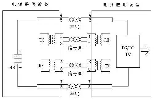
图 通过空闲脚供电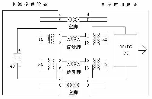 Figure power supply through data pin
When the power supply is applied with the free pin, the 4-pin and 5-pin connections are positive, and the 7-pin and 8-pin connections are negative.
When the data pin is used for power supply, the DC power supply is added to the midpoint of the transmission transformer, which does not affect the data transmission. In this way, the offline pair 1, 2 and the wire pair 3, 6 can be any polarity.
The standard does not allow the application of the above two conditions at the same time. Power supply device PSE can only provide one usage, but power application device PD must be able to adapt to both situations. The standard stipulates that the power supply is usually 48V, 13W. It is easy for PD equipment to provide 48V to low voltage conversion, but at the same time, it should have 1500V insulation safety voltage.
The POE standard also specifies unshielded twisted pair cables for the transmission of electrical power, i.e. Category 3, 5, 5e or 6 cables. It is clear that the existing cable facilities working with it do not need any changes, including category 3, 5, 5e or 6 cables, various short wiring and terminal blocks, power socket leads and connecting hardware, etc. Poe standard is compatible with IEEE 802.3 standard series.
Poe standard defines two methods for using Ethernet transmission cable to transmit DC to Poe compatible equipment: one is called mid span, which uses unused spare pairs in Ethernet cable to transmit DC, and the corresponding endpoint PSE supports Ethernet switch, router, hub or other network switching equipment with POE function. The other method is "end span", which is to transmit DC at the same time on the core wire used to transmit data. The frequency of transmission is different from that of Ethernet data signal. The midspan PSE is a dedicated power management device that is usually placed with a switch. It has two RJ45 jacks for each port, one is connected to the switch by short wire, and the other is connected to the remote device. It can be predicted that end span will be popularized rapidly. This is because Ethernet data and power transmission adopt common line pair, thus eliminating the need to set up independent power transmission special line, which is of great significance for only 8-core cable and matching standard RJ-45 socket.
The figure below is an example of Poe power supply system, which is composed of power supply equipment PSE, power receiving equipment PD, relevant supporting equipment and Ethernet transmission cable.
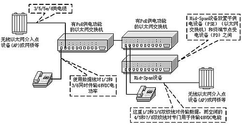
Figure example of Ethernet power supply system conforming to IEEE 802.3af standard
When PD equipment is compatible with POE standard, it can be directly powered from Ethernet cable through RJ-45 socket. For equipment not compatible with POE, DC converter or tap voltage divider can be used to convert its voltage into Poe compatible voltage. These devices are sometimes called active Ethernet splitters, which can take out the DC voltage of the Ethernet cable and supply it to the PD equipment through the conventional DC socket.


Tel: 0086-574-63620701
4008-602-086
Address: No.46, Dongshan Middle Road, Guanhaiwei town, Cixi City, Zhejiang Province
Fax: 86-574-63621610
Email: support@yutai-elec.com
sales@yutai-elec.com